WI-FI 如何传输数据
无线通讯通过电磁波完成,发送端通过电流转换成电磁场,电磁场产生无线电波在空间中传递。利用这现象,将信息调制到无线电波上发送。计算机领域中,信息就是 0/1,通过电磁波的带宽表示(也可以用电磁波其他的概念组合表示,不一定是是带宽)
接收端利用电磁感应原理,通过解调还原成最初的数据,所以 WI-FI 设备都带天线,天线
数据在传输中,发送器会在天线上施加电流,施加的时变电压或时变电流而产生辐射的电磁场,使得电流的能量转变成无线电波。在接收时,天线会由于电场的感应,而在天线内部产生时变电流,并在其终端产生时变电压,产生电讯号经过处理之后,可以在接收器中观察或收听。天线被广泛应用于广播、点对点无线电通讯、雷达和太空探索等通讯系统。天线是无线电通讯系统中的必需组件。
维基百科对无线电通讯有个大体介绍
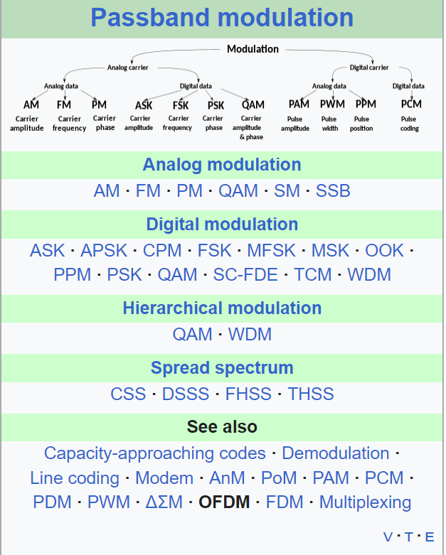
调制解调
WI-FI通过电磁波发送数据,不同的WI-FI版本,a/b/ax/n就是在研究如何调制解调,如何将收到的无线电波解码成多个原始电波
device driver 和 firmware 区别
设备驱动运行在软件层面,OS 级别。驱动是内核相关,不同的内核由于有不同的架构,所以驱动要单独开发
固件运行在具体的外部硬件上,有独立的板载 CPU/RAM/闪存。负责执行 OS 驱动通过 PCIE/GPIO 传递过来的指令,转换为电路表示。由于固件绑定在硬件,所以固件只有一套,始终跟随此硬件,不像驱动,不同的 OS 有多套
Why do firmware and drivers have to be separate? - Super User
不是全部的硬件都有固件,有些硬件逻辑很简单,完全是电路表达,所以不需要固件。一些复杂硬件,比如无线网卡才会单独设计固件,加上微控制器(类似 CPU)执行加减乘除,数据 mov 指令。
固件和硬件绑定,并不会独立向外提供,大多数固件都是闭源的。固件代码需要运行到微控制器,编译器要将代码编译到适合的架构上,比如 ARM/X86,如果微控制器是新的架构,编译器不支持,又需要为编译器支持新的后端
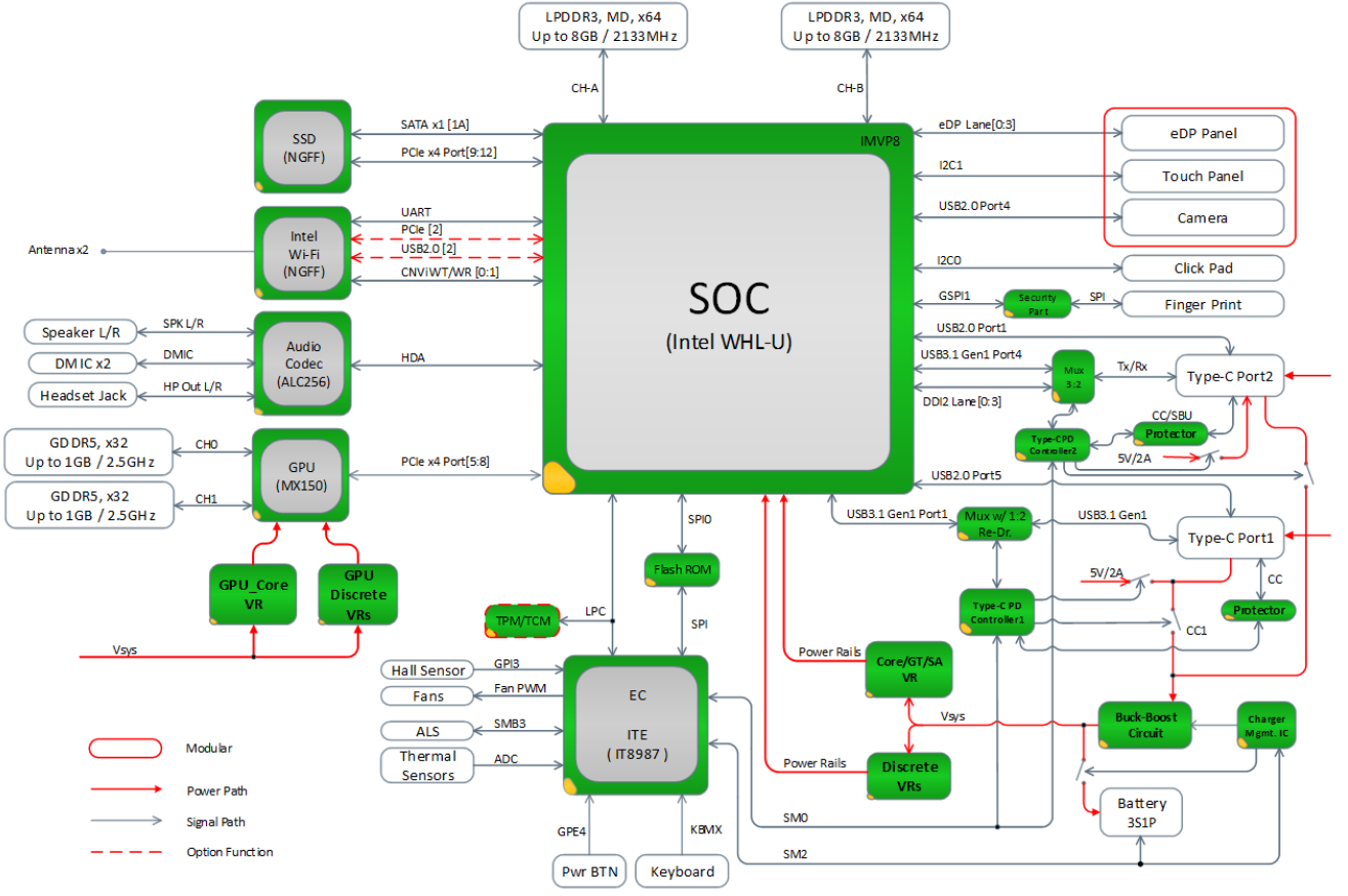
再额外说一句,主板总线可以连接 CPU,RAM,网卡,还有一种工艺是将这些设备都封装进类似 CPU 那种芯片中,被称为 Soc(System on chip)
SoCs are in contrast to the common traditional motherboard-based PC architecture, which separates components based on function and connects them through a central interfacing circuit board. Whereas a motherboard houses and connects detachable or replaceable components, SoCs integrate all of these components into a single integrated circuit.An SoC will typically integrate a CPU, graphics and memory interfaces,[nb 2] secondary storage and USB connectivity, I/O interfaces on a single chip, whereas a motherboard would connect these modules as discrete components or expansion cards.
An SoC integrates a microcontroller, microprocessor or perhaps several processor cores with peripherals like a GPU, Wi-Fi and cellular network radio modems, and/or one or more coprocessors. Similar to how a microcontroller integrates a microprocessor with peripheral circuits and memory, an SoC can be seen as integrating a microcontroller with even more advanced peripherals. For an overview of integrating system components, see system integration.
固件也可以从文件系统加载:驱动程序通过 request_firmware向 kernel 找到所需固件后,再传递给硬件。可以做到对固件的 patch
所以 kernel 要控制硬件,光有 driver 不够,还需要对应的固件程序
总线接口
计算机就是个电路,如何将不同的硬件连接到一起涉及到总线和接口
PCIe 属于内部总线接口/架构,通过 PCIE 接口,外部硬件可以直连 CPU,提升了性能。
https://en.wikipedia.org/wiki/Bus_(computing)#Examples_of_internal_computer_buses
USB 是外部接口,连接计算机外的硬件
https://en.wikipedia.org/wiki/Bus_(computing)#Examples_of_external_computer_buses
当然,这些不过是架构/接口类型,核心在传递数据,主板增加 USB 接口也不是做不到
https://openwrt.org/docs/guide-user/network/wifi/wireless.overview
https://github.com/torvalds/linux/blob/master/drivers/net/wireless/realtek/rtl818x/rtl8180/dev.c
请问下 linux 下的无线网卡驱动开发? - 纸飞机的回答 - 知乎
https://www.zhihu.com/question/31878199/answer/1261285892
一个简单的内核 wireless 驱动
https://github.com/sysprog21/vwifi
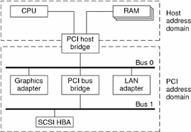
传统主板结构:分南北桥
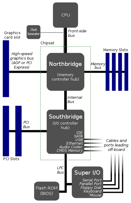
上图可以看到,内存在北桥直接和CPU连接,而外部硬件设备则在南桥,通过PCIE/ISA等总线控制器与CPU间接互联
SOC总线结构将大多数功能都集成在一块芯片,所以 SOC 主板大多数都直连芯片
软件依赖硬件,看明白总线结构,也就明白了很多软件的概念
中断
内核是软硬件交互的接口,驱动需要响应硬件中断。
之前理解外部设备发送中断需要有单独的中断 pin 脚,挂载到总线中断 pin 才能将中断发送给 CPU。局限是 CPU 的 pin 脚数量是固定的,能发起的中断号数量也固定,不能无限制分配。为了支持更多的中断,总线就需要更多的 pin 用于中断。有些设备还需要共享同一个中断,中断触发后驱动轮巡共享中断的设备,设备都去检查自身的状态看中断是不是属于自己的。如果用不了这么多中断号,那多余的 pin 就是浪费。
使用 PCI-E 总线结构的硬件设备支持 MSI,不需要 pin 脚。中断发生后,硬件设备将中断号写入中断控制器的中断寄存器,或者其他 MMIO 的地址。中断控制器再将中断信息通过内存送到 CPU
https://en.wikipedia.org/wiki/Message_Signaled_Interrupts#Overview
开发驱动需要向内核申请中断号并注册中断回调
1 | retval = request_irq(priv->pdev->irq, adm8211_interrupt, |
Difference between request_irq and __interrupt
1 | // 向内核申请中断号 |
并不是每个驱动都要先申请中断号,有些硬件会写死中断号,驱动直接注册中断回调
驱动如何作为内核模块被加载
内核提供 kernel module 来扩展内核能力,驱动大多数是以 module 来开发,下面分析下 driver module 如何注册到内核
经典的 kernel module 注册使用
内核调用 init 初始化内核模块
1 |
|
1 |
|
驱动类型不同,注册的方式也不同,但内部都调用module_driver(__pci_driver, pci_register_driver, pci_unregister_driver)宏
驱动懒加载运行。硬件设备插入内核后,驱动代码才会运行,所以 driver module 将 module_init 导向内核驱动 register 函数
1 | // https://github.com/torvalds/linux/blob/63b823d7d3cd275c3347233f95bdf966a595dbc8/drivers/base/driver.c#L222 |
驱动加载流程
PCI-e 总线结构为例
硬件插入 PCI-E 总线后内核遍历 PCIE slot,读取设备信息,包含硬件 name,vendor,想使用的中断号
从 PCIE controller 读取插在 pcie slot 上的设备的代码调用栈
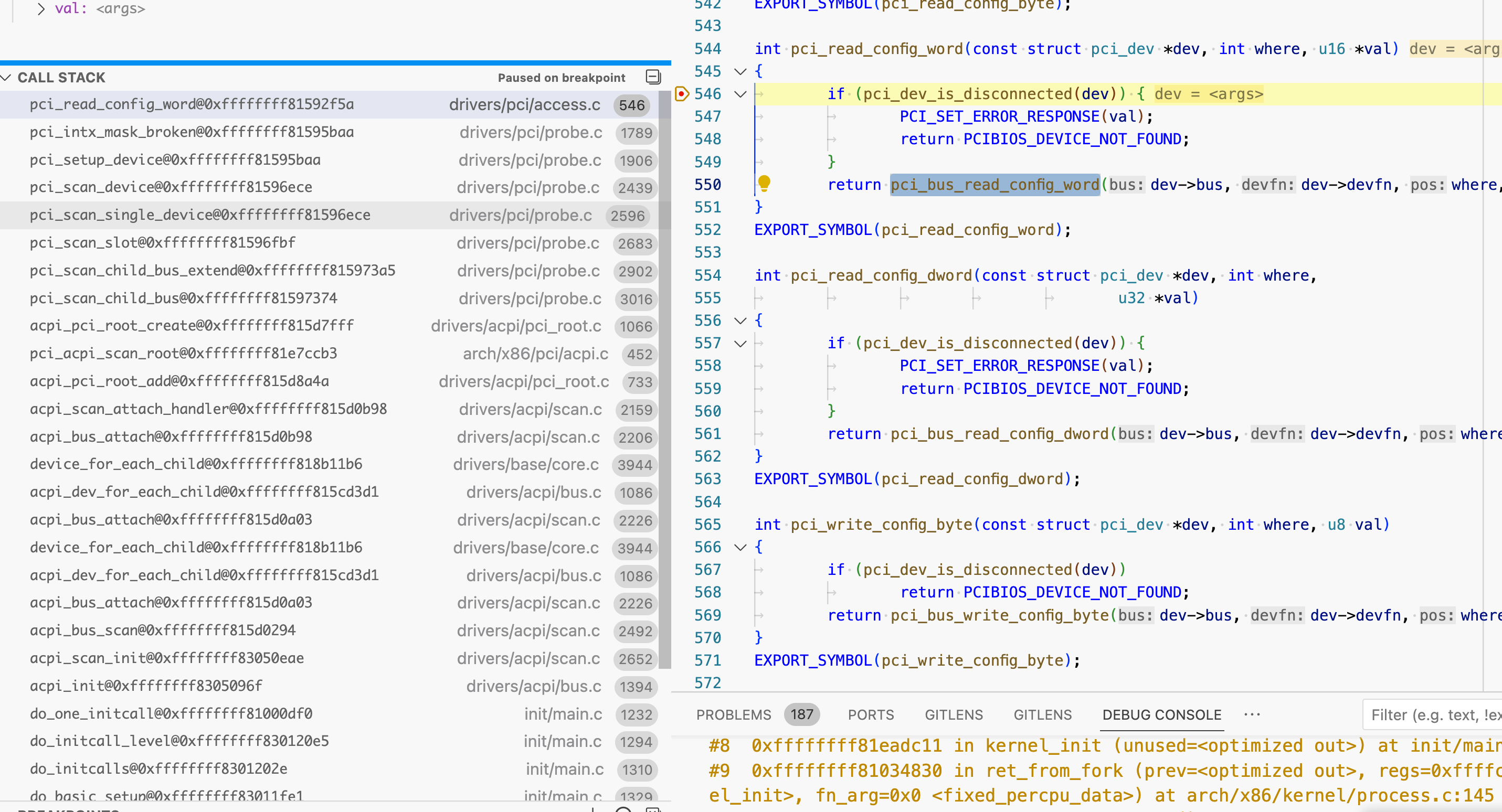
1 | https://github.com/torvalds/linux/blob/69c42d493db452ea87c1ac56e83c978512f4e6ec/arch/x86/pci/direct.c#L21-L50 |
https://www.intel.com/content/www/us/en/docs/programmable/683667/21-1/pci-configuration-header-registers.html
https://en.wikipedia.org/wiki/PCI_configuration_space
https://stackoverflow.com/questions/18854931/how-does-the-os-detect-hardware
1 | // 代码有删减 |
设备信息初始化完成后,依次调用
1 | pci_device_add |
最终调用到内核驱动模块的回调
数据交互的几种方式
- 通过 pin 脚,pinout 的组合数量决定了能够传输的数据量,此种方式要想增加传输的数据量,就需要加更多的 pin
- pin 高电压保持的时间:较少的 pinout 能传递更多的数据,比如约定 pin 1 保持至少 10ns 的高电压则表示 1。局限:传递速度会慢
- 约定数据存放的位置:PCIE 设备会将硬件信息存放到固定的某个地址开始的 256 字节,内核要获取信息只需要读固定位置
- 内存传递:少量 pin 脚标识状态,而将更多的数据存放到约定的地址字段
initcall - kernel init 初始化过程
追踪USB初始化路径时发现 usb_init 并没有显式调用,而是使用宏在 elf 的 .section 新增一条记录
1 | static void __exit usb_exit(void) |
kernel经常会使用 elf 的 .section 进行标记
usb_exit属于initcall的subsys_initcall,在kernel初始化阶段调用。kernel的module有些会依赖kernel子系统初始化完成,所以 initcall 来得比 module_init 更早
initcall在booting时调用,而 module_init 在 load_module调用
1 | /* |
kernel 并不是一定从内存0x0000地址加载,以uboot为例,kernel可以从 0x10000000地址启动
1 | ## Booting kernel from Legacy Image at 02004000 ... |
elf的地址从0开始,kernel计算 启动地址 + .section initcall相对于0的偏移地址 就可以获得 initcall 的实际地址,从而调用initcall初始化
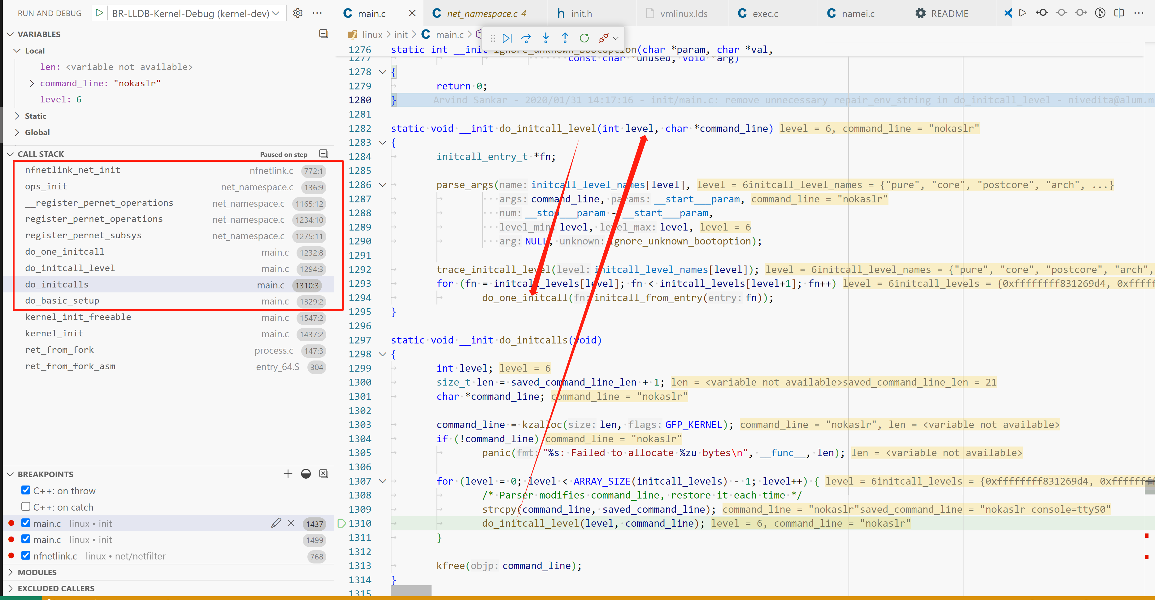
netlink initcall 调用栈
虚拟内存与缺页中断(page fault)
Q: 之前有个疑问,CPU执行process代码采用的是绝对地址,本身汇编访存并没有进行虚拟内存到物理内存转换,CPU是如何发现地址不存在的?
A: 虚拟内存到物理内存的映射不是OS做的,而是CPU内部的内存管理单元(MMU)负责
MMU在CPU内部,kernel和MMU的交互属于 arch-related
在linux源码中,linux/arch/*/mm存放kernel不同架构和MMU的交互逻辑
CPU负责地址映射,需要的地址在页表查不到,会产生 page fault interupt,kernel ISR(interupt service routine)检查缺页中断,将内存页从磁盘复制到内存,将调入的内存块在MMU中建立映射
https://en.wikipedia.org/wiki/Memory_management_unit
https://en.wikipedia.org/wiki/Page_table#Page_table_entry
https://zhuanlan.zhihu.com/p/488042885构建不需要MMU,进程使用物理地址访问内存的kernel https://popovicu.com/posts/789-kb-linux-without-mmu-riscv/
内核和用户进程一样也使用虚拟内存,内核分配函数分配的也是虚拟内存。和用户进程不同的是,内核还控制页表,当内存找不到访问页,kernel负责页换入/换出
https://www.kernel.org/doc/Documentation/DMA-API-HOWTO.txt
The kernel normally uses virtual addresses. Any address returned by
kmalloc(), vmalloc(), and similar interfaces is a virtual address and can
be stored in avoid *.
DMA(直接内存访问)
https://blakerain.com/blog/allocating-memory-for-dma-in-linux
IOMMU

https://www.kernel.org/doc/Documentation/DMA-API-HOWTO.txt
If the device supports DMA, the driver sets up a buffer using kmalloc() or
a similar interface, which returns a virtual address (X). The virtual
memory system maps X to a physical address (Y) in system RAM. The driver
can use virtual address X to access the buffer, but the device itself
cannot because DMA doesn’t go through the CPU virtual memory system.In some simple systems, the device can do DMA directly to physical address
Y. But in many others, there is IOMMU hardware that translates DMA
addresses to physical addresses, e.g., it translates Z to Y. This is part
of the reason for the DMA API: the driver can give a virtual address X to
an interface like dma_map_single(), which sets up any required IOMMU
mapping and returns the DMA address Z. The driver then tells the device to
do DMA to Z, and the IOMMU maps it to the buffer at address Y in system
RAM.
DMA访问不经过CPU,自然就不会经过CPU内部的MMU。IO设备通过虚拟内存访问内存数据就无法进行,为了解决此问题,在总线上引入了IOMMU,作为MMU的替代负责虚拟内存到物理内存的转换
在一些架构上,dma_address可以是物理地址,但大多数情况下,都是bus address。设备需要IOMMU进行地址变换,才能访问到真正的RAM DMA地址。注意,bus address不是虚拟地址,可能是其他类型的地址,因为IOMMU负责地址变化,谁知道它怎么映射的呢,没准是任意的地址
kernel 使用物理地址记录外围设备的io地址,驱动无法使用,它需要 ioremap() 成虚拟地址,变成 memory mapped io address
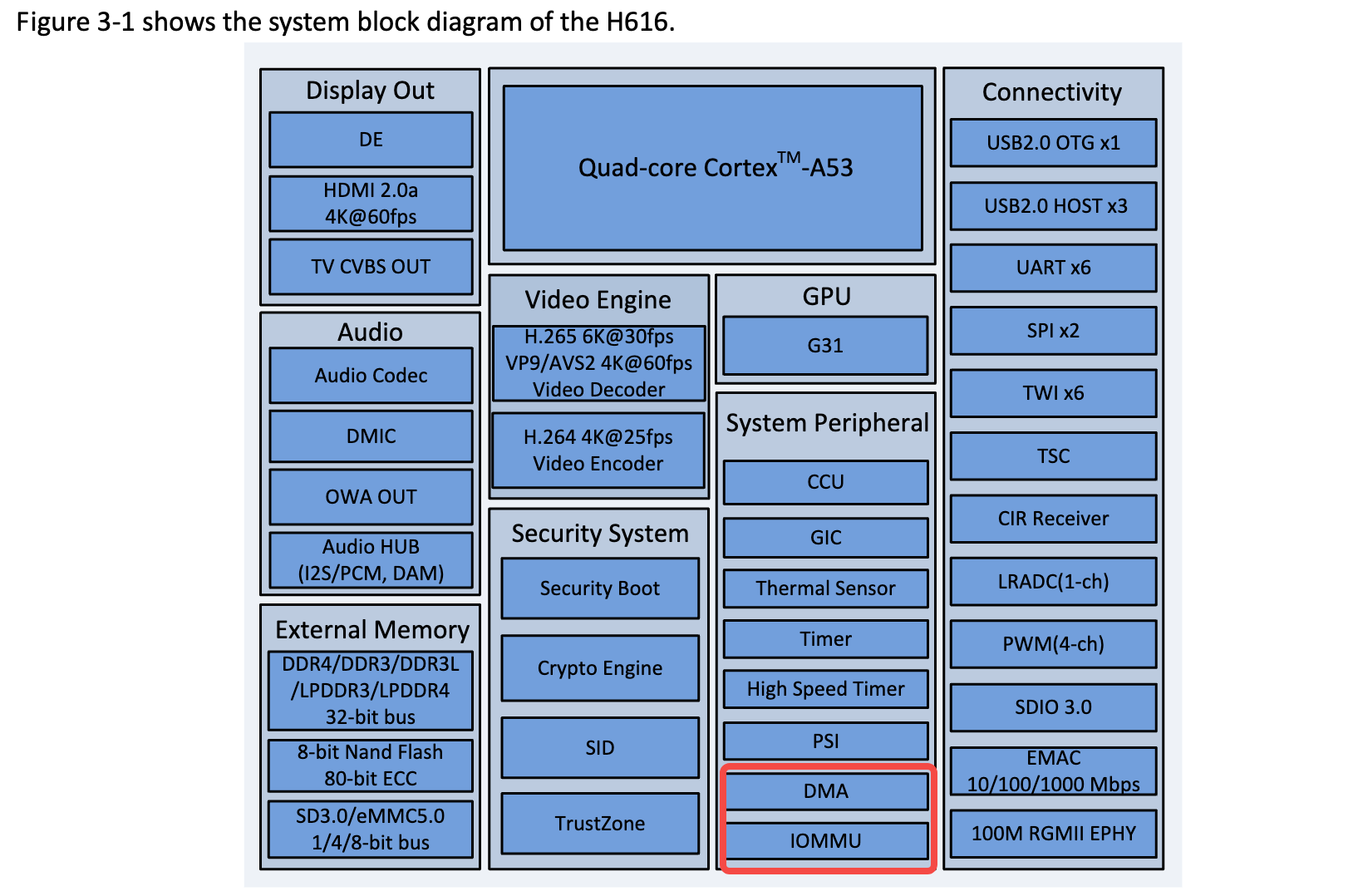
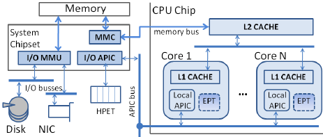
IOMMU和DMA控制器可以集成在主板,也可以集成到SOC,比如 H616 SOC
驱动和设备通过DMA descriptors ring buffer通讯。device控制head,driver控制tail
每个buffer存放指向 data 的指针,device将收到的数据放到data,driver从ring buffer取走(如果是net driver,创建skb_buff push到内核协议栈),创建新的buffer,加到descriptor ring buffer 的tail
ixy-writing-user-space-network-drivers
其他的userspace driver实现,不一定对齐Linux
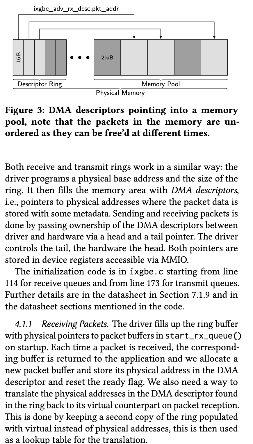
Both receive and transmit rings work in a similar way: the
driver programs a physical base address and the size of the
ring. It then fills the memory area with DMA descriptors,
i.e., pointers to physical addresses where the packet data is
stored with some metadata. Sending and receiving packets is
done by passing ownership of the DMA descriptors between
driver and hardware via a head and a tail pointer. The driver
controls the tail, the hardware the head. Both pointers are
stored in device registers accessible via MMIOReceiving Packets. The driver fills up the ring buffer
with physical pointers to packet buffers in start_rx_queue()
on startup. Each time a packet is received, the correspond-
ing buffer is returned to the application and we allocate a
new packet buffer and store its physical address in the DMA
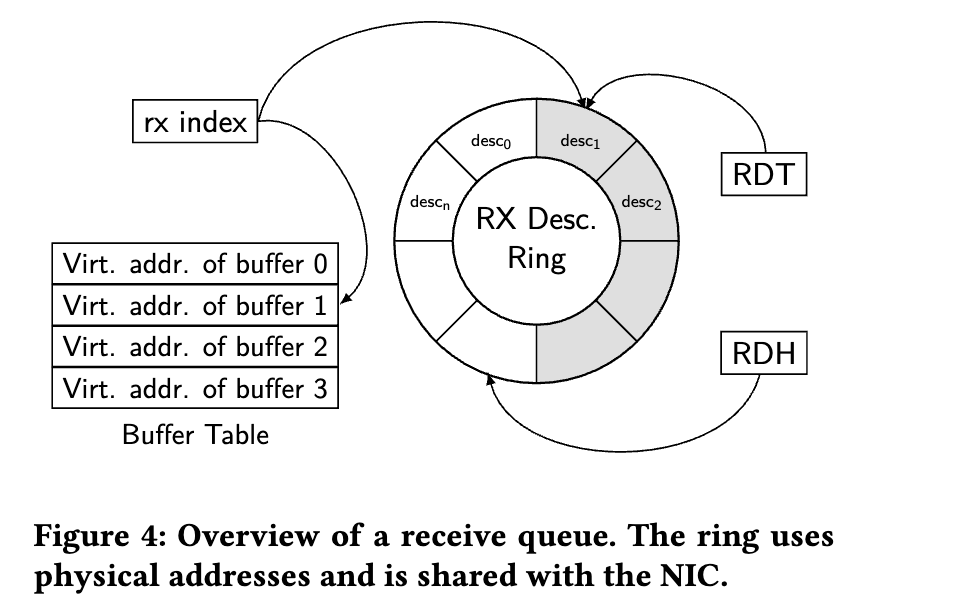
descriptor and reset the ready flag. We also need a way to
translate the physical addresses in the DMA descriptor found
in the ring back to its virtual counterpart on packet reception.
This is done by keeping a second copy of the ring populated
with virtual instead of physical addresses, this is then used
as a lookup table for the translation.
DMA desc ring
虽说一直提到DMA ring buffer,但DMA并不一定需要ring buffer。DMA提供双方互相访问的内存。DMA对双方在内存中以何种数据结构进行通讯没有强制要求,你可以用DMA内存实现ring buffer,将DMA address写到硬件。也可以用其他结构。
ringbuffer好处是容易实现 lockfree list,硬件和驱动分别从头和尾取/放 buffer
总而言之,DMA只是硬件和驱动直接沟通的媒介,怎么沟通那是两方的事。
虚拟地址,物理地址,总线地址
物理地址:CPU物理地址
总线地址:host bridge的整个地址空间,外围设备的地址(IO地址)都在总线地址上
虚拟地址:CPU虚拟地址
CPU是如何分别访问内存地址和外围设备的IO地址的?
CPU 有单独的引脚标识此次内存访问是RAM,还是IO地址
如果引脚高电压,访问的地址是IO地址,否则为RAM地址
总线控制器负责将访问重定向
https://stackoverflow.com/questions/44237345/how-does-the-cpu-writes-data-to-an-io-port
重新思考就会发现,内存访问不单单是访问 0xffff 那么简单,中间必然夹杂着其他协议。比如PCI-E 总线,访问地址时会涉及到PCIE总线通讯协议
网卡接受/发送队列
网卡有多个接受/发送队列,收到/发送的数据按照一定算法分配到不同的队列,充分利用CPU多核心的特性,不同核心从不同DMA buffer取数据。网卡有网卡芯片和ROM中存放的机器指令
1 | // https://github.com/torvalds/linux/blob/v6.6/drivers/net/wireless/mediatek/mt76/usb.c#L628 |
GRO(Generic Receive Offload)
和GRO相似的是LRO(large receive offload)
核心原理:
将小包组装成大包再交给协议栈,减少协议栈处理包的数量,降低处理压力
LRO会合并看到的全部包。但小包的TCPHeader可能不尽相同,如果合并成一个TCP包肯定有header要被丢弃,造成数据失真,甚至有些数据包及其依赖TCP header trick,合并会破坏原本的通信。
GRO是LRO的升级版。
原理:
为每种合并都定义合并规则,只有当这些数据字段相同才合并。
所以GRO有很多类型,针对IP_GRO,TCP_GRO,VxLAN-GRO。
拿IP举例,如果涉及packet reordering,合并也会取消
合并规则如下
https://github.com/torvalds/linux/blob/v6.6/net/ipv4/af_inet.c#L1509
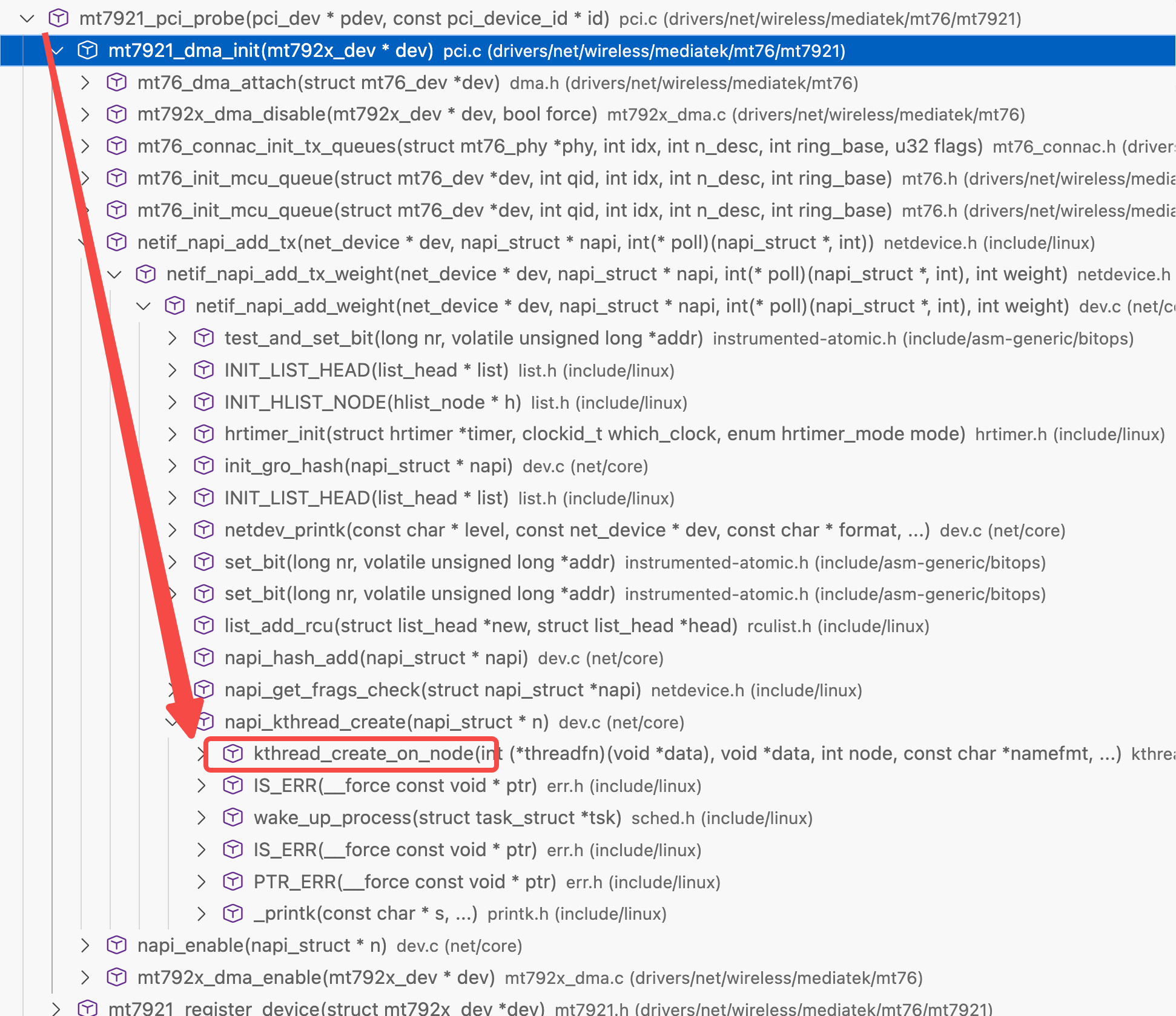
NAPI
基于已有thread_struct封装的新的任务调度库
kernel thread通过thread_struct调度,napi本身封装了thread_struct,内部有kernel thread
驱动初始化代码里创建napi结构,kernel会创建对应的调度上下文,napi 被 kernel调度执行,最后回调驱动代码
为什么NAPI收到第一个包需要关闭中断?
每收到一个包就触发中断会导致极高的CPU占用。NAPI模型采用polling方式避免了大量的中断触发
RCU(read copy update)
基于一点,对指针长度的内存数据写入是原子的。只有两个值,新值或旧值,没有中间态
如果地址总线长度32,那么针对对齐后的4字节写入是原子的
c - Does a CPU assigns a value atomically to memory? - Stack Overflow
如果32长度,写入64长度数据,CPU不得不拆分成两次就不是原子写入
指针长度往往等于地址总线长度。可以认为:现代CPU中,对齐后的指针写入是原子操作
https://www.kernel.org/doc/html/next/RCU/whatisRCU.html
In contrast, RCU-based updaters typically take advantage of the fact that writes to single aligned pointers are atomic on modern CPUs, allowing atomic insertion, removal, and replacement of data items in a linked structure without disrupting readers.
但还是需要 atomic interger
CPU存在缓存,读取没有中间态,但读写有新旧之分,多核对同一内存值相加,结果不一定符合预期
If aligned memory writes are atomic, why do we need the sync/atomic package? | Dave Cheney
参考
kernel.org/doc/Documentation/RCU/checklist.txt
pdos.csail.mit.edu/6.828/2023/lec/rcu-faq.txt
READ-COPY UPDATE: USING EXECUTION HISTORY TO SOLVE
CONCURRENCY PROBLEMS
总结:
volatile int foo;:最初给IO内存使用,IO内存访问有严格的顺序,确保foo的访问不会被reorder,每次访问都生成访存指令,修改后的值对其他CPU可见,编译器可以reorder其他 non-volatile值的访问。
如果希望foo的访问在bar之后,光volatile不够,还需要加内存屏障
__memory_barrier/__sync_synchronize
Compile-time memory barrier implementation
Runtime memory ordering
Why is compiler allowed to reorder instructions around system calls? : r/cpp
原则上 volatile 和memory barrier是两个东西,现在的编译器提供的内置sync函数默认都会添加full memory barrier
比如
GCC __sync_bool_compare_and_swap - IBM Documentation
Clang Clang Language Extensions — Clang 18.0.0git documentation
atomic算是volatile和memory_barrier的合体。store/load 接收ordering参数,能够更细粒度控制 memory ordering,依赖CPU架构提供的指令(x86的LOCK_总线同步)
硬件中断/软中断/tasklet/threaded irq
硬件中断优先级最高,内核需要马上停止其他工作来执行硬件中断handler。handler执行时间过长会影响系统稳定性,于是硬件中断handler将其他的工作以软中断的方式进行,tasklet就是依赖软中断的一个系统。软中断并没有自己的上下文,直接运行在kernel上下文,所以无法被像thread一样调度,执行时间长会影响稳定性。
现在逐渐废弃 tasklet,将handler都变为thread,由kernel调度器统一执行调度
如果全部软中断执行的时间太长,每个CPU单独的ksoftirqd会负责执行其他的软中断work。ksoftirqd会通过线程来执行软中断
中断处理程序(ISR)运行在哪个 CPU core?
结论;中断控制器决定哪个core运行 ISR,当然,事无绝对,system boot阶段如果有中断会默认发送core0。
x86有APIC,APIC通过总线连接CPU进行通讯
还是那句话,计算机是人造的,解决问题的方法千千万,现在使用的方法清楚就行,不要抱着“为什么是这种方式,而不是那种”,就是选了这种方式罢了
x86 - How does the CPU decide what core should handle a hardware interrupt? - Stack Overflow
multiprocessing - Multi-core CPU interrupts - Stack Overflow
multiprocessing - Multi-core CPU interrupts - Stack Overflow
根文件系统
initial-rootfs是只读的,只用于kernel启动的初始化过程。有kernel Image,必要的二进制,比如 /sbin/init
初始rootfs必须能被bootloader访问,可能是rootfs自身,又或者放在引导分区内
bootloader才能获得kernel image和初始rootfs,并将他们放到内存并启动kernel
kernel启动后判断初始rootfs格式,选择挂载(ext2),还是先解压再挂载(cpio),可以从userspace系统获取必要的驱动,模块,初始化程序。
kernel内核态初始化完成后结尾调用 sbin/init 初始化用户进程。init进程根据 fstab(或者其他配置) 对 / 进行remount,重新挂载(remount)为磁盘憋处的真正文件系统(比如ext4)
想想就行了,如果全流程都用initial rootfs,你修改内容每次都要重新更新它,或者再其上添加overlay
现在debian也只会在某些情况,比如升级kernel版本,才会调用 update-initramfs 更新initial rootfs,给kernel启动时用
initrd vs initramfs
initrd: initial ram disk
initramfs: 就叫 initramfs
内存对齐
内存是线性的,但是逻辑上的线性,和实际的存储方式并不关联。线性内存方便从软件角度理解内存
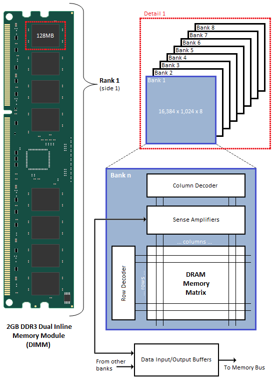
内存条结构如下
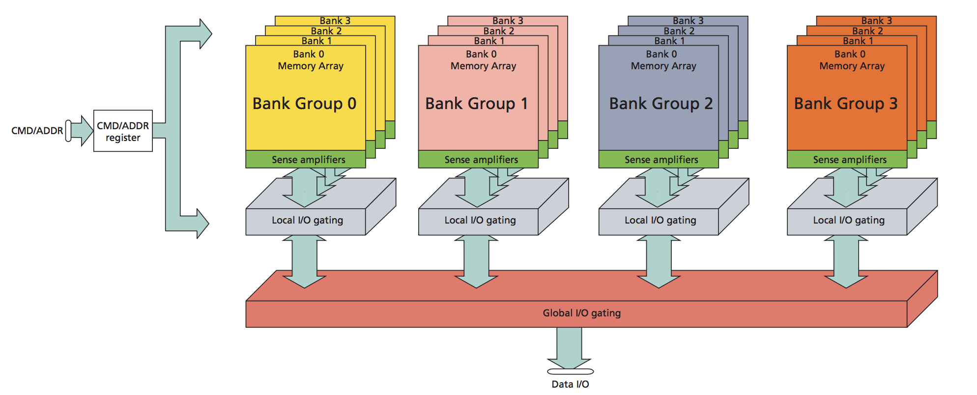
内存访问结构如下。
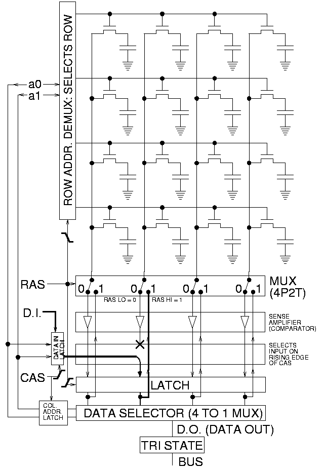
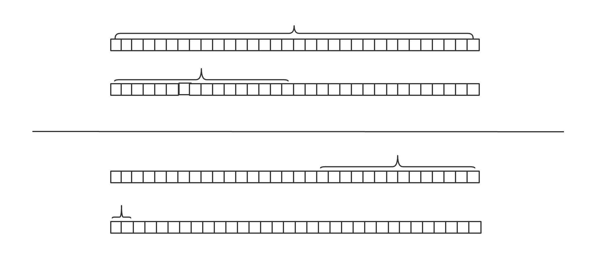
32位地址总线,CPU是32位寄存器。一次至多传递4字节数据。矩阵式排列最适合逐行扫描,一次性访问4字节,控制器一次就可以扫描完成
非对齐访问需要跨行访问,控制器先扫描第一行,将前两字节数据放到寄存器的低两字节,再扫描第二行放到寄存器高两字节,同样读取两字节,非对齐需要两次操作
引用
MHVLUG_2017-04_Network_Receive_Stack.pdf